
Overview
The main electrical functions required by the controller were tilt sensing, sound sensing, button & switch inputs, LED indication, and radio communication. Each of these systems were either housed completely or directly wired to electronics module, which contained the Tiva and all power distribution.
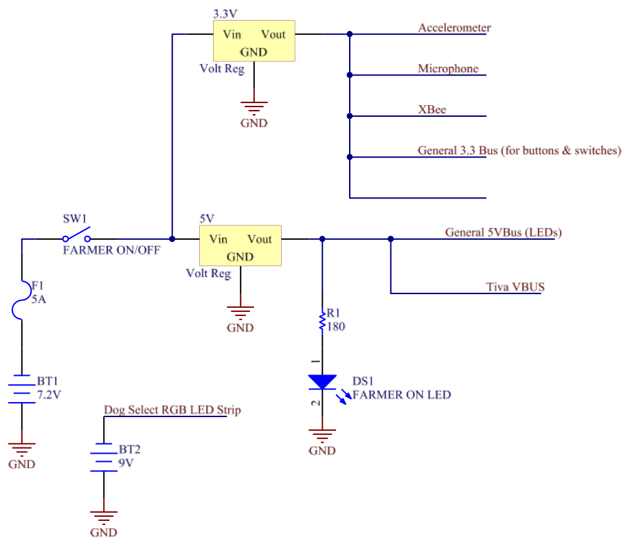
Power DistributionPower for the controller was provided by a single 7.2V NiCd battery. Two voltage regulators were used to segment this power into a 3.3V supply for sensor logic and 5V supply for powering the Tiva and indicator LEDs. A separate 9V battery was used to supply power to the RGB LED strip within hovercraft select cup.
|
| ||
Tilt Sensing
A simple 3-axis analog accelerometer (ADXL335) was used to translate tilt along two independent dimensions into two analog voltage signals. These signals were filtered and amplified before being processed by the Tiva's built-in ADC and scaled to determine the inner tube's forward/back and left/right tilt.
| Tilt.pdf |
Conch Microphone
A microphone was mounted within the conch shell and used to pick up the user blowing into the shell to initiate pairing. The signal was filtered, amplified, passed through a peak-detector circuit to extract volume information, and run through a Schmitt trigger to create a digital signal.
| Microphone.pdf |
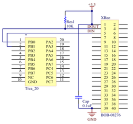
Radio CommunicationFor radio communication, an Xbee transceiver was wired to the UARTs lines of the Tiva. A pull-up resistor was used to insure the RX line of the Xbee remained high.
|
| ||
IMU LED Display
|
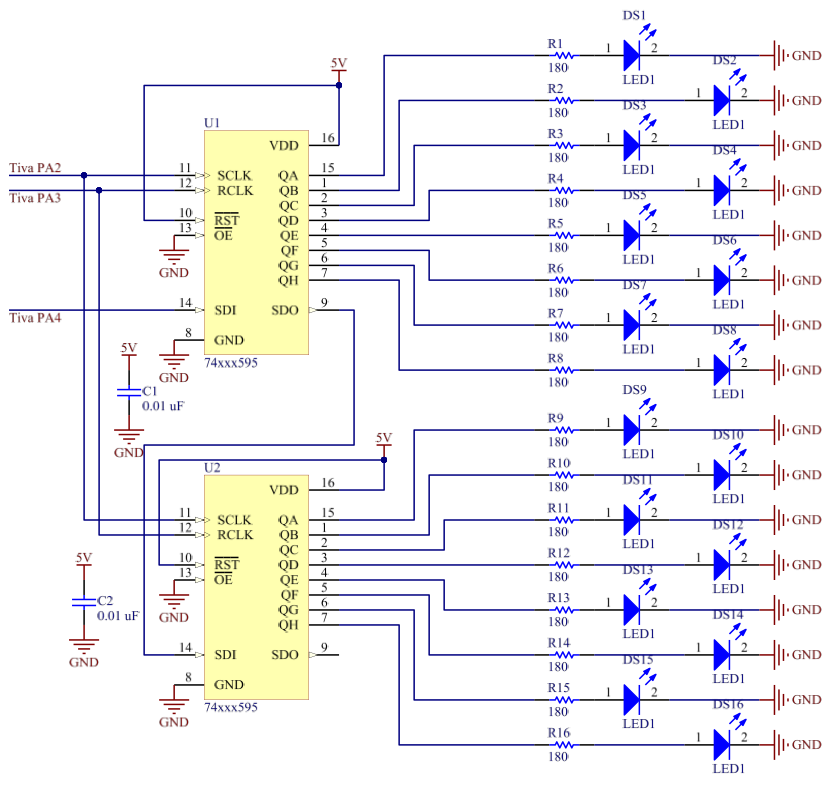
To display IMU data from the hovercraft, we opted to use an array of 16 LEDs to visualize spin rate in the Z direction. If the bot was not spinning, the green LEDs in the center of the display were illuminated. If the bot was spinning counterclockwise, the left LEDs would incrementally illuminate proportional to the spin rate. Likewise, the right LEDs would illuminate during clockwise rotation. Two daisy chained shift registers were used to individually control each LED.
| ||
Hovercraft Select
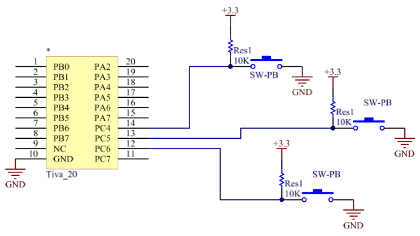
Three roller switches were used to detect if the user had placed the palm tree in Slot 1, 2, or 3, which correspond to hovercraft 1, 2, and 3 respectively.
| HovercraftSelect.pdf |
|
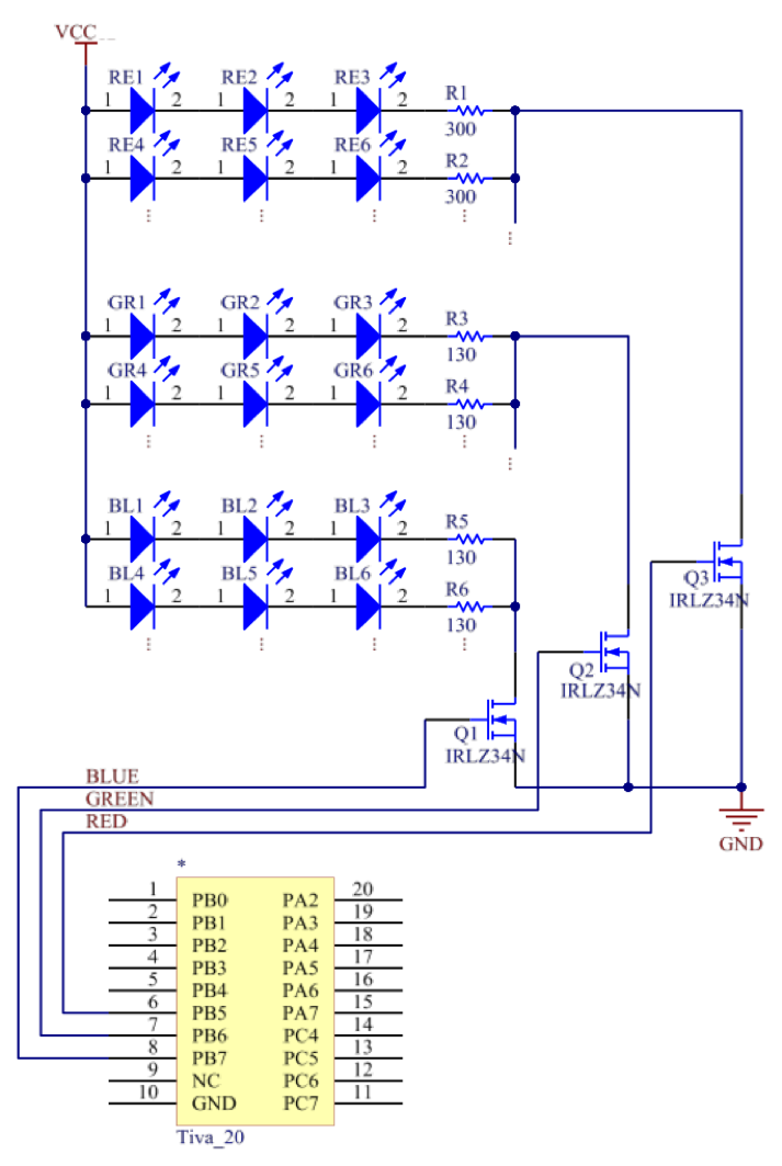
Indicator LEDsAn RGB LED strip was used to indicate the controller's pair status with either hovercraft number 1, 2, or 3, illuminating a different color for each. A power MOSFET was used to control current through the R,G, and B lines of the strip, which was powered via 9V battery.
|
| ||
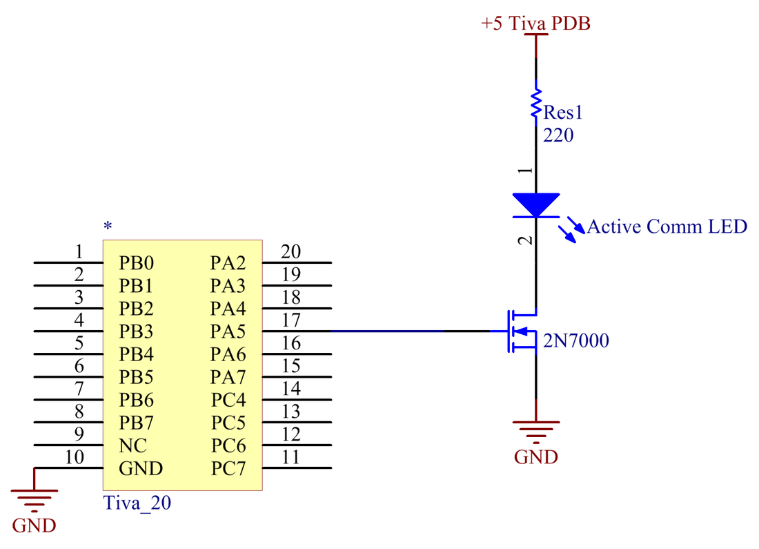
Active Communication LED
|
This LED is pulsed when a packet is received from the hovercraft that this controller is paired with.
|
| ||
Battery Life Calculations
Based on the circuit components used for our FARMER, we expect about 12 hours of battery life. See calculations below.
| Battery Calculations (Excel) |
