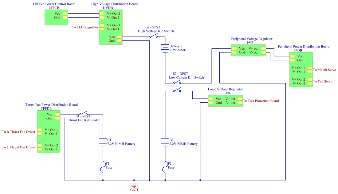
Main Power Circuitry
The DOG used 3 total batteries. Two were combined in series and provided electrical power for logic, servos, lift fan, and LED strips. The other battery provided power exclusively to the thrust fans. Three switches controlled power as follows: Thrust Fan Kill Switch (Thrust Fans), Low Current Kill Switch (Logic and Servos), and High Voltage Kill Switch (Lift Fan and LED strips). Logic power supply was managed by the Tiva protection board (supplied by ME218).
|
| ||
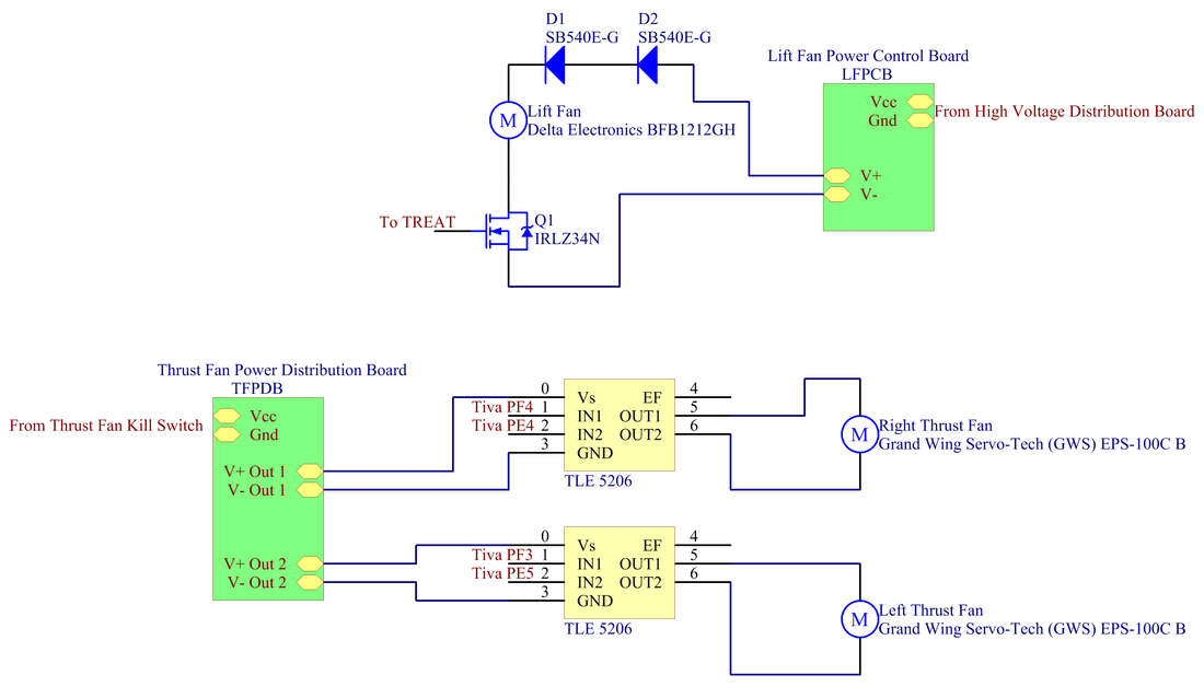
Fan Circuitry
The power to the lift fan on our DOG was controlled by the TREAT from a PIC microcontroller. The series combination of two 7.2V batteries exceeded the max rating of 13.2 VDC for the lift fan, so two SB540E diodes were placed in series with the fan to step down its supply voltage. The thrust fans were each controlled by a TLE 5206 H-Bridge, and received power from a single 7.2V battery. Each of the thrust fans was capable of bi-directional motion.
|
| ||
Peripheral Circuitry
One of the signature features of our hovercraft was its peripheral "shark bite" function. The operator could trigger the hovercraft to close and open the shark mouth, accompanied by flashing mouth LEDs to emphasize the bite. In the unpaired state, the shark's mouth was closed, and upon pairing, the mouth opened to expose the first-person view operation camera inside. In both the paired and unpaired states, red mouth and blue body LEDs flashed for visibility and to provide information about the shark's current state. To signal the paired state, the shark tail started a swimming motion upon successful pairing.
The circuitry for the LEDs consisted of LED strips controlled by an N-Channel MOSFET in low-side drive. Two servos controlled by PWM straight from the TIVA drove the mouth and tail movements. Power for the LED strips and servos were provided by two separate +5V and +12V voltage regulators.
The circuitry for the LEDs consisted of LED strips controlled by an N-Channel MOSFET in low-side drive. Two servos controlled by PWM straight from the TIVA drove the mouth and tail movements. Power for the LED strips and servos were provided by two separate +5V and +12V voltage regulators.

|
| ||
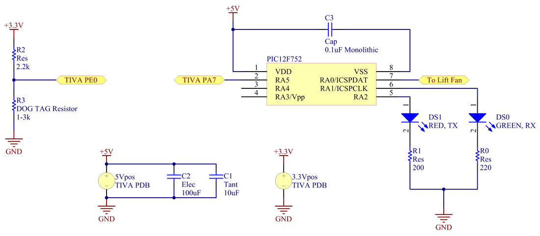
Fan Control Microcontroller (TREAT) and DOG TAG
The PIC12F752 received asynchronous communication from the TIVA, raising and lowering the lift fan and green LED lift line as commanded by the TIVA. The red LED illuminated for 0.25s each time a valid lift fan command was received from the TIVA. Shown at left, a simple voltage divider to the analog input line PE0 was used to identify whether a 1, 2, or 3k resistor was in place as the DOG TAG. The DOG TAG was used to indicate which robot the DOG was to identify itself as for communication.
|
| ||
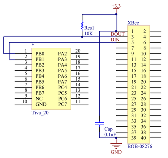
Radio Communication
For radio communication, an Xbee transceiver was wired to the UARTs lines of the Tiva. A pull-up resistor was used to insure the RX line of the Xbee remained high.
|
| ||
IMU
An inertial measurement unit (IMU) communicated with the Tiva via SPI. A double hex inverter circuit was used for the serial data line because of signal strength issues encountered prior to amplification.

|
| ||
