Tuesday, May 29
LED and Peripheral Completion, Checkoff
LED and Peripheral Completion, Checkoff
- Added LED strips to mouth and base
- Added timing code for LED flashing and peripheral mouth chomp
- Tested interoperability with various teams
- Checked off
- All components mounted and finalized in FARMER and DOG
Sunday, May 28
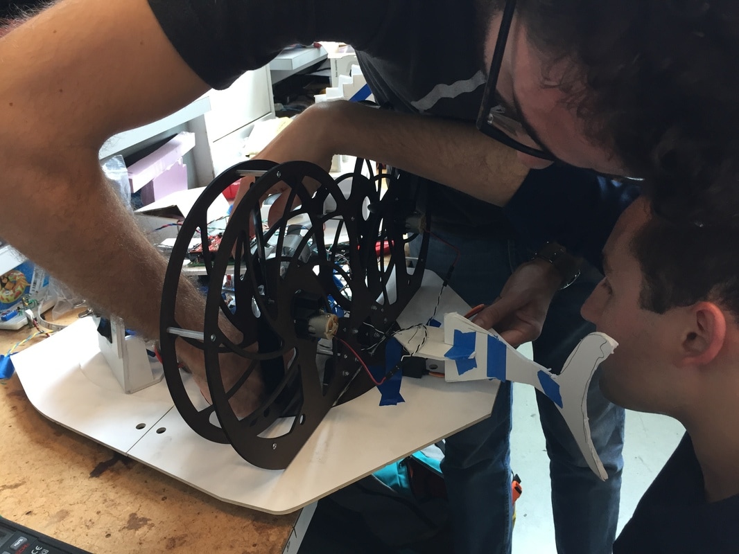
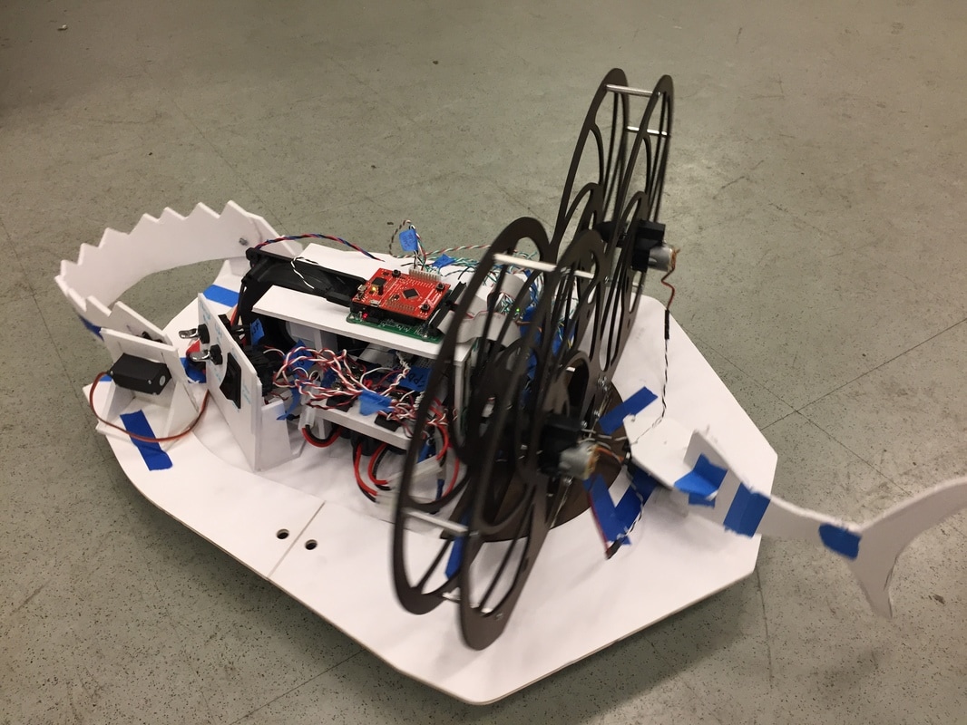
Shark Assembly
Shark Assembly
- Mounted tail and shark costume
- Conducted several test runs
- Decided to add LEDs
- Began stuffing and mounting components into inner tube
Friday, May 26 - Saturday, May 28
System Testing and Shark layout
System Testing and Shark layout
- Confirmed interoperability with multiple teams DOGs/FARMERs
- Began covering DOG with shark costume
- Implemented peripheral/brake functions
- Fabricated shark mouth assembly and painted mouth and thrust fan frame
- Began fabricating components for mounting and integration
- Constructed the straps and the system to hold them in place on the inner tube
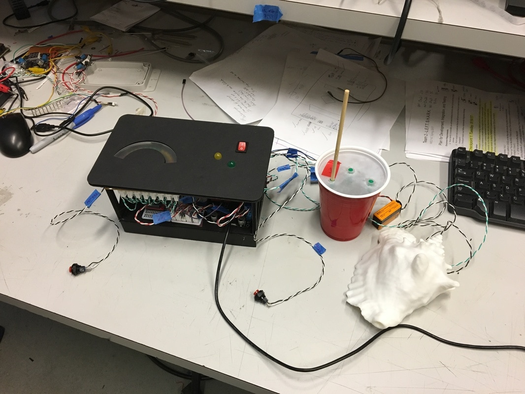
- Fabricated conch mount
- Used plastic tubing for wiring harness
- Successfully controlled hovercraft using only FARMER module
|
|
|
Thursday, May 25
DOG Revisions
DOG Revisions
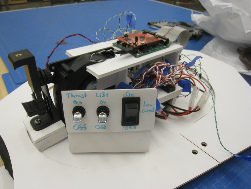
- Re-made connector for TREAT/ lift fan power control board
- Installed a switch bay for power control
- Completed thrust fan frame and mouth design, laser cut out of duron, assembled, and tested
- Mounted electronics in module
- All FARMER electronics soldered and finalized
Wednesday, May 24
Weebly problems
Weebly problems
- During content upload, discovered that logbook content was missing
- Had to remake entire logbook from beginning
- Lasercut a new bot chassis, dubbed "SharkBot"
- Placed boards on new body
- Constructed a "Tiva deck"
- Assembled module structure
- Opted for magnetic lid design
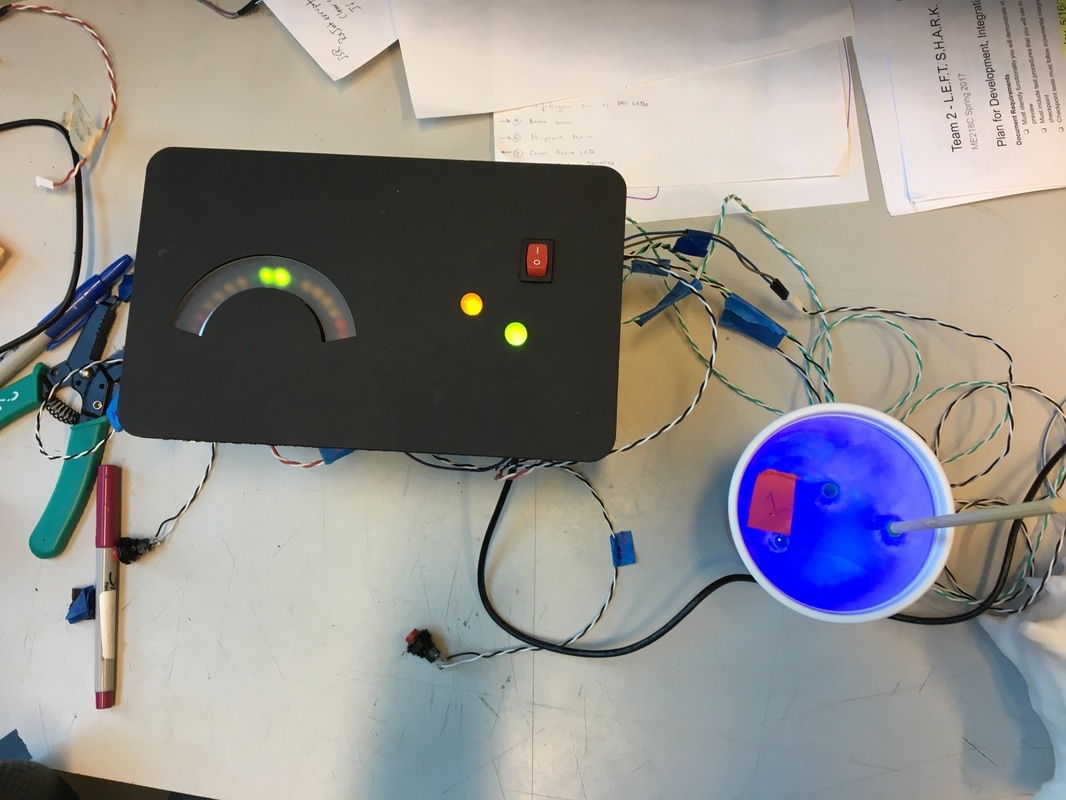
- Mounted and soldered IMU LED display
Tuesday, May 23
Layout Revisions
Layout Revisions
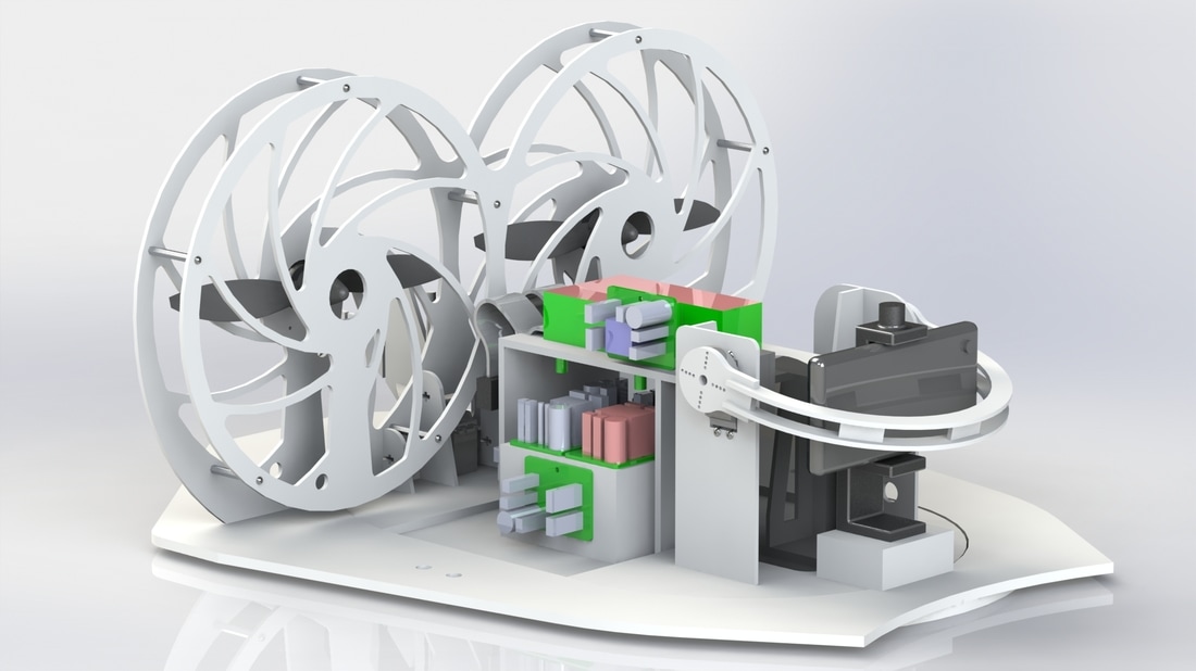
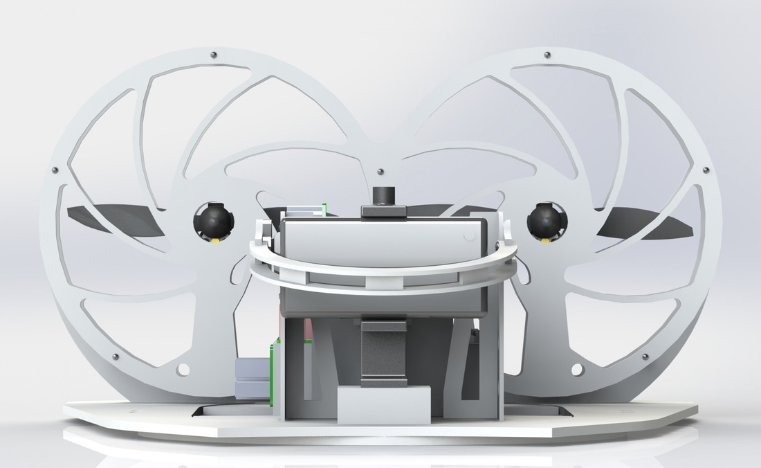
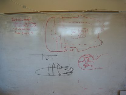
- Discussed new chassis layout and considerations for
- Fan
- FERRET catcher
- Bumper
- Completed chassis CAD for LaserCutter reservation tomorrow
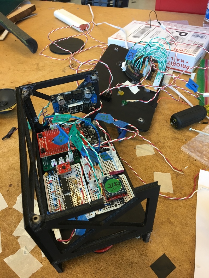
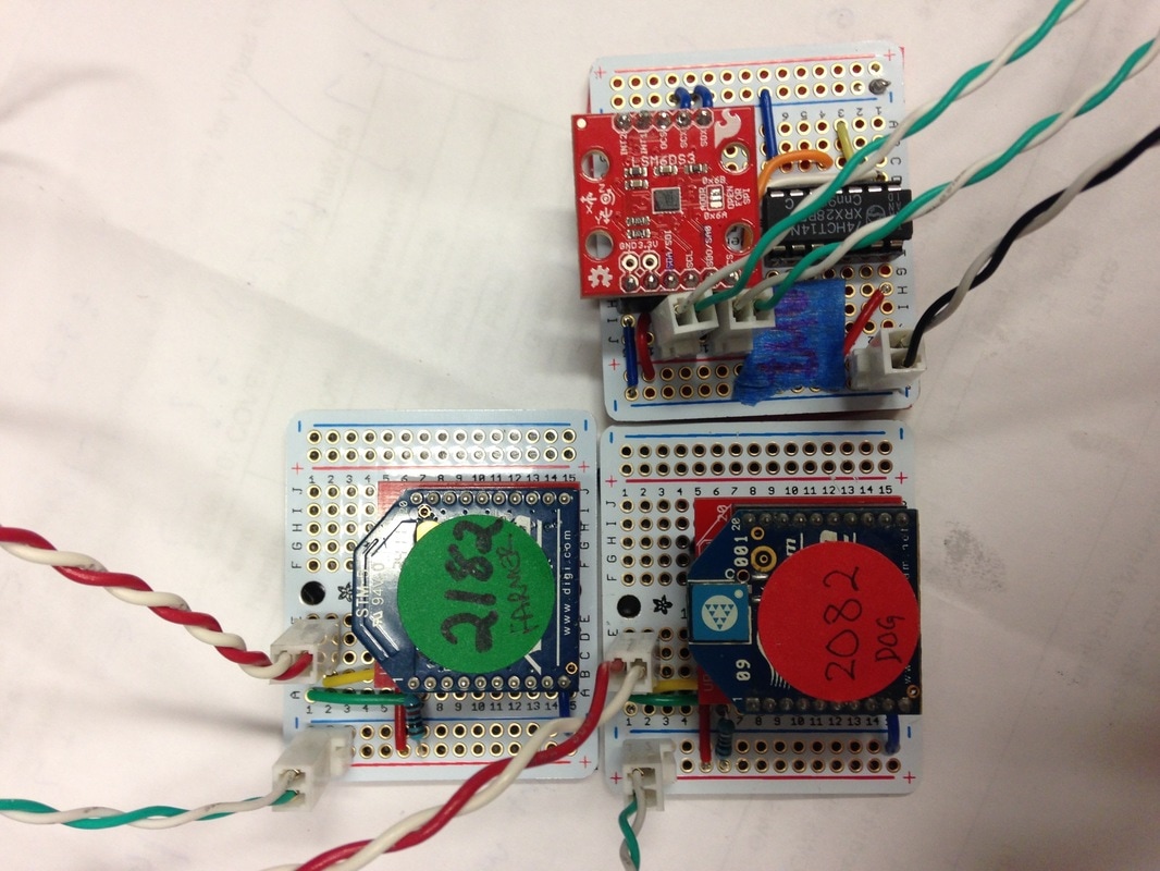
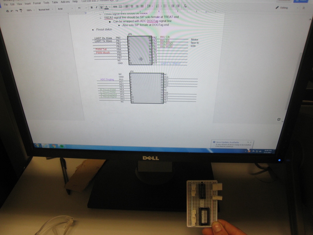
- Completed logic distribution board for directing Tiva signals to DOG boards
- Moved FARMER and DOG XBee circuits and the IMU circuit from breadboards to soldered on protoboards
- Laser cut electronics module structure from foam core
|
|
|
Monday, May 22
Remote Thrust Control
Remote Thrust Control
- Used accelerometer to remotely control DOG
- Validated driving control algorithm
- Determined that control algorithm must be modified
- Successfully displayed IMU data from DOG on the FARMER LED test-setup (see video)
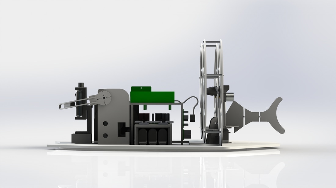
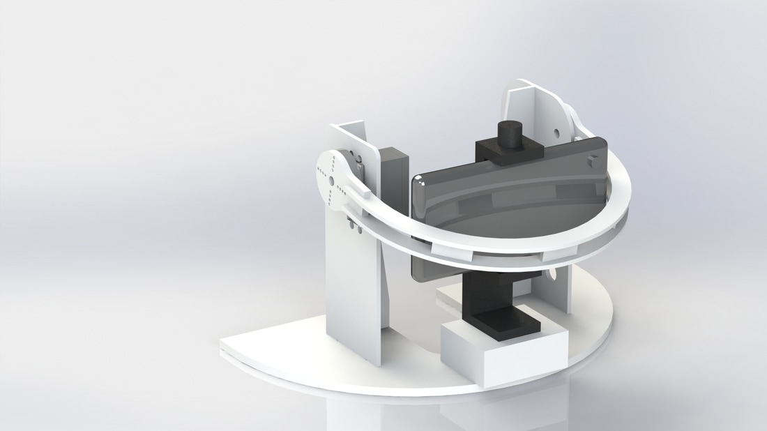
- Designed CAD for electronics module in inner tube
Sunday, May 21
Mouth/Tail Prototyping and TREAT Progress
Mouth/Tail Prototyping and TREAT Progress
- Implemented electromechanical display via shark mouth/tail
- Began developing TREAT for lift control
- Connected the DOG-Select cup (with LEDs), the accelerometer, and the pairing mechanism
- Soldered and mounted microphone circuit
Saturday, May 20
Electrical completion and Shark Tail Experiments
Electrical completion and Shark Tail Experiments
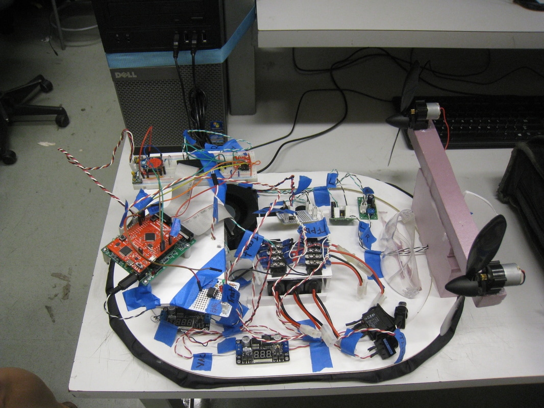
- Put relevant electrical components onto HoverBuddy
- Conducted SpinTest
- Determined TLE chips must have <7V for logic inputs
- Discussed driving control algorithm
- Completed circuitry and housing of DOG select mechanism
|
|
|
Friday, May 19
Power Circuit Completion and HoverBuddy Construction
Power Circuit Completion and HoverBuddy Construction
- Soldered TLE circuits
- Completed power circuit for DOG
- Made thrust motor stands from pink foam
- Dubbed "HoverBuddy"
Thursday, May 18
Power Circuit Progress
Power Circuit Progress
- Continued fabrication of power circuit for dog
- Consulted TLE from past project for wiring of H-Bridge
- Soldered accelerometer circuit
- Implemented tilt service in software
Wednesday, May 17
Power Circuit Fabrication
Power Circuit Fabrication
- Purchased spade connectors and switches from Ace hardware
- Began soldering power distribution busses
- Prototyped DOG select cup from laser cut acrylic and straws/chopsticks.
Tuesday, May 16
TLE Purchase
TLE Purchase
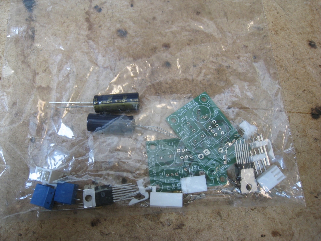
- Purchased TLE5206 H-Bridges for bidirectional thrust fan control
Monday, May 15
Proposed DOG revisions and Power Circuitry
Proposed DOG revisions and Power Circuitry
- Discussed locations for components and circuits on DOG
- Considered a horizontal fan orientation (taken from other groups)
- Designed and 3D printed conch shell
Sunday, May 14
Digital Control Testing
Digital Control Testing
- Sent a pair request to HoverBuddy from terminal and Xbee
- Ran abridged state machine that turned on lift and thrust fans digitally
- Generated square wave from microphone sensor
- Used accelerometer to generate analog signal
- Checked off
Saturday, May 13
Initial Prototyping Success
Initial Prototyping Success
- Made hovercraft from lasercut foam core board
- Tested lift fan
- Yielded near-frictionless hovercraft, dubbed "HoverBuddy"
- Sent a pair command over Xbee
- Discussed systemic functionality and composed state machines
- Prototyped LED display
Thursday, May 11 - Friday, May 12
Power Circuit Development and Initial Prototyping Efforts
Power Circuit Development and Initial Prototyping Efforts
- Constructed circuit for battery power of lift fan
- Made several rounds of prototypes
- Learned that lift fan must go outside of skirt cavity
- Experimented with skirt designs
- Successfully prototyped accelerometer and microphone circuits
Friday, May 5 - Wednesday, May 10
Purchasing and Preliminary Hardware Testing
Purchasing and Preliminary Hardware Testing
- Bough propellers and motors from AeroMicro
- Bought skirt Nylon from Joann fabrics
- Began testing circuitry for motors
Wednesday, May 3 - Thursday, May 4
Project planning and ideation
Project planning and ideation
- Discussed general content ideas
- Decided on Shark Theme
